Tuesday, April 14, 2020

Installation and commissioning of IP CCTV Cameras


For Installation and commissioning of Internet Protocol (IP) Based Closed Circuit Television (CCTV) Cameras a list of devices are used. Their working and configuration will be explained below along with the screen shots of each and every step.

Before starting the real connections, network devices are configured because all of them are IP based and if any IP clash with the IP of other device the system will not work even if the connections are accurate. Hence, I will start configuring the network devices one by one. Firstly, I will start with the configuration of IP Camera. For my project I am using IP Camera of Make Dahua and below I will tell all the steps I have followed to configure it and provide it a unique IP Address.

CONFIGURATION OF IP CAMERA: 

Model: DH-IPC-HDW12B0SP-L
Make: Dahua

This camera is 2 MP IP Dome camera (used in indoors) with 3.6 mm lens to capture wider view.
The image of the camera is as below:

Dahua 2MP IP Dome Camera (IPC-HDW12B0SP- L)


Each company have some default IP addresses for their devices and this camera have the default IP of 192.168.1.115. For configuration of IP cameras, they need to be opened in the laptop. For this, I gave power to the camera through a 12 V 1.5 A power adapter by simply inserting the DC pin inside the DC port of the camera and connected the other end of the camera through a Cat-6 Patch cable directly with the Laptop as shown in the image.


After attaching it to the laptop, I started the configuration of the camera, for this, I had to open the camera through the IP on the LAN network and hence, I checked if the IP is active and responding me on the system by using the run command as below:

Firstly, I pressed Windows+R and a dialog was opened as below:


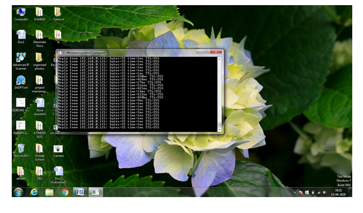
Once opened, I tried to ping the default IP address of the camera but using the command ping 192.168.1.115 -t as shown in the image.


Upon pressing the enter after writing the command, I did not got any response and the screen showed request not found. But without getting any reply from the IP, the camera's configuration was not possible. So, I tried something else.


I then opened the Network and sharing center from the extreme right bottom where Wifi signals were shown.

Then I double clicked on the WiFi network opened the details of the WiFi network and found various options to consider. The screen looked like this:


 Then, I started exploring the different options and when I clicked on the details of the network, I found out that the IP address series that my network was using, was completely different from the default IP of the camera. Its default gateway was different from the default gateway of the camera's IP. Hence, I was not getting any reply from the IP of the camera because both of them were unable to communicate. Default gateway of the camera was 192.168.1.1, however, the Network's gateway was 192.168.0.1. Their IP series were also different: Camera had the IP of 192.168.1.115 whereas network's IP was 192.168.0.142.


 Then, I understood the reason why I was not getting any response. Then again, I went to the other option called properties, because I had to manually change the properties of the network I am using to establish a communication between the camera's IP and the IP of the network.


 After that, I clicked on Internet Protocol Version 4 (TCP/IPv4) and was directed to another window.


 Here, in general settings, the first option was already selected to obtain an IP address automatically, but here I had to manually change the IP and the gateway to make communication between the camera and the system. Hence, I changed the IP address of the network to 192.168.001.25 and the default gateway to 192.168.1.1.


 When, I saved those settings and checked again the response on the run command prompt I got the reply from the camera as shown in the image. Now, the communication was established and one of my difficulty was resolved.


 Again, I opened the Internet explorer and checked if I can access the camera through its IP or not. But, as I had got the reply, I was confident that I can access the camera now. I entered the IP 192.168.1.115 in the address bar and by pressing enter I got the view as below. Then, I entered the username and password and tried to login the camera by using its default username and password. But unfortunately, I could not login, not because of wrong username and password but because of the default permissions in windows, that does not allow any third party .exe file to execute and block it for security purposes.

Again, I had a new challenge to face and to resolve the issue. Because I knew the problem was due to lack of permissions right. I went to internet options to check the rights I am having and change them accordingly.


I clicked on the security tabs and noticed internet protection mode was enabled and only custom level option was there. Hence, I just clicked on that to check the rights.


 When the tab opened, I noticed a lot of options there were disabled and almost all of them were restricting any new software to open and download.


 I enabled them all and saved the settings and again refreshed that page and entered the IP to check if there is any progress?

Then, I entered the username and password there and again tried to logon the camera.


As all the permissions were enabled I could easily login now and change or modify the settings of the camera to make it use able with any standard NVR.


 But before that, I noticed, I am still unable to get the view of the camera on the laptop as it was asking for some plugin to install. I clicked on the link to download that plug in and run and saved it in my system. However, every time, I tried to download it, it was again blocked for security reasons and I started getting windows alert that this software may harm my system. It look me think again and go back to the previous permissions page to check if any setting is still disabled?


Before going back again, I changed the IP of the camera to make it accessible in my system without manually changing the IP and default gateway of the WiFi network, which was a very daunting and lengthy process. Hence, I went to setting tab in the top right row of the window and clicked on the setting. There, I jumped to network settings and opened TCP/IP sub option. There I changed the IP address of the camera to 192.168.0.115 and default gateway to 192.168.0.1. Rest of the settings are as below:  Then the camera restarts and the IP was changed to the new one i.e. 192.168.0.115.


Pinging the new IP that is 192.168.0.115, I get the reply and now, my camera is online.


Then, I tried to login it again but now with the changed IP, a pop up appeared asking allowing Dahua Technologies Co. Ltd plug in, I allowed it.


After allowing the plugin to install, when I logged on, I got the Live view of the camera as shown in the image.


Then, I went to the settings tab where the first option is camera and under it two sub options were there: First is Conditions where camera's Brightness, contrast, saturation, Sharpness, Mirror, Flip: all options can be altered according to the view.

Second is Video, under this option various sub categories are there as shown in the image provided, in video, main stream and sub stream videos resolution, bit rate, frame rate and many more can be altered according to the our requirement.

other option is snap shot, where one can save the snapshots of either recording or the Live view , which can be later used for varies purposes. In overlay, one can save any name of the camera to have a better knowledge about the area where the camera is installed.


In path option, we can select the path where we want the snapshots or the recording to be saved.

Second option now is of Network, where TCP/IP is the first option and here we can manually select the IP of the camera to avoid any IP conflict and take the view on the LAN network. For my camera, I have selected the following IP address, Subnet mask and default gateway to establish a connection between the network and the camera. Here, I have selected the mode to be static instead of DHCP as I am selecting manual IP address for my camera and DHCP changes the IP every time it is rebooted.

Other network setting is port where I have saved the following port numbers as shown in the attached screenshot. Where TCP port is 37777 and UDP port is 37778, HTTP port is 80 and finally HTTPs port is 443. I saved the following configuration.


Final setting under network tab is Access platform, where I have selected P2P, It is a cloud ID and it has a unique serial number and QR code as well, as shown in the image below;


Third option is Event, under this, first one is video detection and video tamper, which can be enabled and further the vulnerable area or region can be selected by pressing area and selecting periods for each day and save them according to the requirement. Region can be selected and named as Red, Yellow, Blue and Green zone and can be saved. 


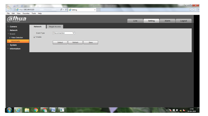
Under abnormality tab, alerts will be sent if any network issue occurs like disconnection to alert the user and check their network connection to avoid any mis-happening.


Under illegal access tab, the access will be blocked if several attempts were made to access the settings of the cameras and login error attempts can be set from 3 to 10 times.


In System settings, general name, language and time and date of the camera can be manually set.


In Account setting, User name and password of the camera cab be altered as well as Onvif User settings can be selected by the user.


In default, the camera can be brought to its default or factory settings.


In Upgrade, the firmware or software of the camera can be upgraded by using an external USB drive or by selecting the software and browsing it through the computer or laptop.


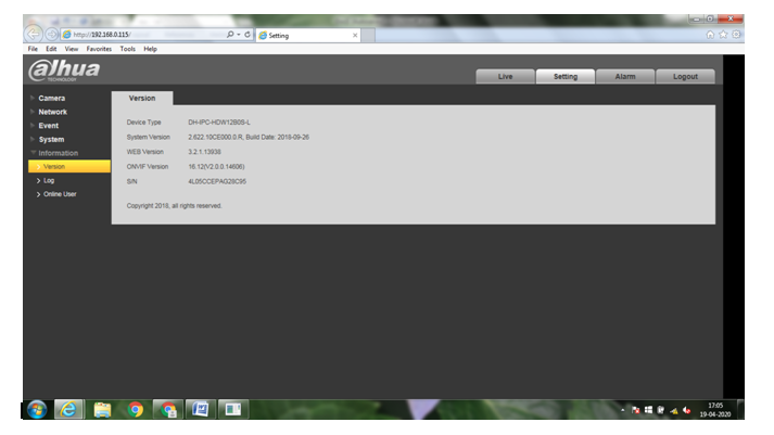
At last, the information tab tells the version of the camera including its model number, system, web. onvif version.

Online user will tell the IP address of the number of remote locations where the cameras are currently online and are viewed.


Third option of the camera is Alarm, where the alarms can be set at different places like, when there is any motion detection, video tamper or illegal access, or while any new operation is taken place. The alarm tone can also be manually selected by browsing through the location.


Monday, April 13, 2020

Installation of Biometric Access Controller:


For the installation and commissioning certain steps need to be followed, which I am explaining below along with the screen shot of the functions of the Biometric Machine:


Realtime Biometric Machine

Firstly, the finger print of the authorized persons are enrolled in the machine manually by pressing Menu.

The following options will be displayed:
 Register, Delete, Set Comm, LockCtrl, Advanced and View Info
           
Each Option have their different functions and will be explained one by one below:


 1. Register: It has different options like Uer, Admin, Sup-User and U-Upload. Each and every function will be explained one by one. Firstly,


  • User: To enroll the authorized person's fingerprint and provide them access to enter the house. In user further two options are there: New Reg. for registering new user and BackUp to take backup of all the enrolled users.  In New Reg, various other functions will pop up like Finger (by scanning fingers on the scanner), ID Card (by showing RFID card near the scanner of the machine), Password (by setting an Eight digit passcode), FP and Card (requires both fingerprint and Card), FP and Pass (requires both fingerprint and password); One can enroll users in any of these ways and provide them authorization to enter. 1500 Users can be assigned in a single machine.


  • Admin: To give authorization to a single person to alter its settings without the finger of the manager or admin, machine menu will not be displayed and ask for authorization. In admin as well, same two options as in user will be displayed; New Reg. for registering new user and BackUp to take backup of all the enrolled admins.  In New Reg, various other functions will pop up like Finger (by scanning fingers on the scanner), ID Card (by showing RFID card near the scanner of the machine), Password (by setting an Eight digit passcode), FP and Card (requires both fingerprint and Card), FP and Pass (requires both fingerprint and password); One can enroll users in any of these ways and provide them authorization to enter. Maximum of 10 admins can be assigned here.


  • U-Upload: The data can also be transferred into the machine by uploading an excel file containing all the details via USB or by software of the biometric. For this, U-Upload function is used.


2. Delete: As the name suggest, it is used for deleting the users by entering their ID nos which is eight digit from 00000001 to 9999999. It will again ask for confirmation if pressed Yes, the users details will be deleted from the machine.


3. Set Comm: It stands for Communication settings, which has three options like U-Down, RS485 Dwnld and Ethernet. This feature helps to establish a communication between the machine and the admin via USB(which is commonly used everywhere) or RS485 (This is used to get details where USB is not allowed like in defense sector or a corporate with additional security) or Ethernet (Where data is accessed remotely).


  • U-Down: Here the data can be downloaded with the help of a USB it has various other options to get the selected data as shown in image: Glog and Del (To get the log reports and along with the restored data), All Glog (To download all the records), Slog and Del (To download all the management records along with the restores ones), All Slog (Downloads all new management records), Enr. Data (Download all the enrolled Data)


  • RS485 Dwnld: Here data can be download via RS485 Connector as it is widely used in data acquisition and control applications where multiple nodes communicate with each other and it is used to download data with RS485A and RS485B Ports and the baud rate can be adjusted as well like 9600, 19200, 38400, 57600 or 115200.


  • Ethernet: To download the data from the machine remotely by using Ethernet setup, it also has various settings to transfer data online through networking cables. Different options in the machine are: DHCP: No (By Default), IP Address (192.168.001.224), Subnet Mask (255.255.255.0), Default Gateway (192.168.001.001), Port No: 5005, Server Req: Yes, UseDomainNm: No, Server IP, SerPort No. 7005; HeartBeat: 3


4. LockCtrl: It consists of all the controls of the Electromagnetic Locks that is connected with the machine through cables and unlock times can be set up through these settings. It has various options as such, Unlock Time (It gives the time the lock of the machine will stay open once its open allowing access to the user which is 5 Seconds by default but can be altered); Lock Type Set can be chosen from the options as such No for the Alarm Type which is no (by default) but can be changed to NO (Normally Open) or NC (Normally Closed); Alarm Delay (Its 10 Seconds by default) but can be changed. Third option is of Wiegan (26 by default), it is communication protocol that connects the access control device with the third party device to send the IP or data through the cable or by RF Reader which is the biometric machine, in this case.


5. Advanced: It basically have four options: Device, Logs, Set Time and Bell.


  •  Device: It has basic device settings like Machine ID (Any from 1 to 65536), Admin Quantity (Any from 1 to 10), Language (like English, Chinese, Russian and many more), Volume (from 1 to 10), Screen saver (Yes or No), Dormancy (Yes or No), Verify (F/P/C or C+F or F+P), Upload UI (User Interface via USB Port), Shut Down (To Shut down the machine), Default Setting (To Bring all the settings of the machine to default) and finally, Manager Cancel (It will cancel or delete the manager or admin finger print from the machine).


  • Logs: It will give warning messages, once the data limits of the machine is achieved: ARec Wrn: All Record Warning which is 255, once the data logs reaches that value they will give warning messages to delete the old logs and make way for new logs. URec Wrn: 1000, ReVerify: No (It is set as default No but can be set to maximum of 9999 Seconds).


  • Set Time: In Set Time option, the date and time of the machine can be set up and the date format can be set as YMD or MDY or DMY.


  • Bell: In Bell options the value of Count can be set from 0 to 255 as maximum, and a total of 8 time slots can be set when there will be bell ring from the machine.


6. ViewInfo: This option displays the information of the machine and has three different options, like Storage Detail, Record Detail and System Detail.


Storage Detail gives the details of the number of data (users, managers, Finger Prints, Passwords and RFID Cards) present in the machine.


Record Detail gives the number of users and admins data present in the machine. It also shows the User records and the same can be deleted from there as well.


System Detail gives the details of the system as below:


Now, the first stage is complete that is programming of machine and then the next step is connecting it with the Electro Magnetic Lock and push to exit button:

The machine have 10 Pins and each pin is of different color and has different function. The table below shows the different pins with its description and color coding:

PIN
DESCRIPTION
WIRE
1
RS485B
WHITE
2
RS485A
BLACK
3
WG-IN0
GRAY
4
WG-IN1
PURPLE
5
NC
GREEN
6
COM
BLUE
7
NO
ORANGE
8
PUSH
YELLOW
9
GND
RED
10
POWER
BROWN


As I am doing normal connections of Biometric Machine with Em Lock and Push to Exit, I will ignore the first four wires and connect the rest of them according to the following circuit diagram:

Connection diagram of Em Lock and Push to exit with the Biometric machine

This set up will provide access to the building only after scanning the finger print. This is the first stage when only the authorized person will enter the premises.

Devices used along with their Working:

1. Biometric Machine: This machine will be used as a reader to check if the user is authorized to enter the premises or not. Once the user place its finger on the sensor, the sensor will match the fingerprints received with the number of finger prints enrolled in the machine, once the match is found the Machine will acknowledge by saying Thank You and consequently open the lock for few seconds (whatever we have assigned in the lock time option) after that again the lock will be closed. Here the machine is used only as a reader but can be used for various purposes like taking attendance and also giving punch reports to calculate the working hours of the individuals and their salaries as well by using software, but in my project I am using it just as a READER.


2. Power Supply: As the name suggest, power supply is used to provide power to the devices we are using like Biometric Machine, Electro Magnetic Lock and Push to Exit Button. The system mainly works on 12 V DC, hence, this supply changes the mains AC current into 12 V DC to provide desired powers to the devices attached with it. Here I am using a single power supply of 12 V 5 A for all devices. 


3. EM Lock: Electro Magnetic Lock also works on 12 V DC, it has two terminals positive and negative to make the connections and allowing the current to flow and establish a connection between the machine, power supply and the Lock itself. Once the biometric reader checks the person's authorization the lock will open or close providing access to the building through the door where it is installed. Depending upon the type of the door, the bracket is also selected like L Bracket, U Bracket or ZL Bracket. Sometimes Rim locks are also used to provide access.


4. Push to Exit Button: As the name states, pushing this button allows access. However, it is placed only near the manager's desk so that the manager can give access to a person manually even if the person is not authorized, just by pressing this button the locks will be opened and the circuit will break allowing access, however, it should not be misused. For this as well, we need to use a bracket to fit it near the manager or admin.


5. Cable: Normal 2 core cable can be used to make all the connections as all the external devices has only two ports positive and negative. So, it can be used easily. Depending upon the distance of the machine, lock and exit switch normally 10-20 Mtr cable is enough for its installation.


CONNECTION AND WORKING OF THE SETUP:

Connection: 

RS485B and RS485A ports are used to transfer data to and fro machine, here, as I am not taking any kind of data I will leave the ports open and instead use USB to collect data from the machine.

WG_IN0 and WG_IN1 ports are used for third party transfer, which I am not using here, hence, I will leave these ports open as well.

Now, Firstly, I will provide Power to the Biometric Machine, for this, I need a power supply. Here I am using 12 V 5 A supply having only two terminals that is Positive and Negative. Then I will connect its positive terminal with the Brown pin of the machine which is for Power and the negative terminal to the ground (GND) which is Red in color. In this way, the circuit will be completed and the connection between the machine and supply is made to make 12 V DC flow inside and provide power to the machine.

Then again, connecting EM Lock with the machine. It also has two terminals negative and positive having red and black color respectively. Negative terminal that is Red in color is connected to the ground (GND) terminal of the machine by connecting it with the negative terminal of the power supply and then routing it to the GND of the machine, as shown in the figure. The positive terminal of the machine is connected with the NC (Normally Closed) having Green color, in this the circuit is completed and the connection between the Machine, Lock and the Power supply is established.

Finally, connecting push to exit switch with the machine. This switch has two terminals Positive and negative. The Positive terminal is connected with the PUSH wire in the machine, which is Yellow in color and the negative terminal is connected directly to the GND (Ground) of the machine along with the negative of Lock and supply. In this way, the connection will be set up among Biometric Machine, Em Lock, Power Supply and Push to Exit button.

Apart from this, common port (COM) of the biometric machine that is Blue in color is shorted with the positive terminal of the power supply and is connected to the machine routing it through the + ve terminal of 12 V power Supply.

The above figure explains the connections. Now the working part:

Working: 

This system works on a simple system. Initially, the user will place the finger on the sensor of the biometric machine and if the user is already enrolled in the machine or authorized to enter then the machine will acknowledge by saying thank you and the em lock connected with the machine will open it for few seconds (which was already set in the lock time option in the machine). At that time, the person can enter the house, once the user enters the lock will again come back to locked stage and ask for authorization to any other consecutive entry. If the person is not authorized to enter then it will simply deny access and barres the person to enter. This is the first security stage to save the properly and the assests of the house holder.


In the second stage, I am installing the IP CCTV Cameras to capture the image of the intruder and the steps will be explained in the next post.